

Pneumatic-hydraulic power units
KRATOSPACK: a guarantee of quality
A new range of pneumatic-hydraulic power units, designed and manufactured entirely at our Italian facility, for applications requiring high thrust and high positioning speed.
The design features, drawing on over 30 years of experience, are the result of 2 applied techniques: Pneumatic actuation in the approach to the workpiece and the return to rest position, along with hydraulic force amplification during the operating phase.

HLU - HLX
Pneumatic cylinder and hydraulic multiplier mounted coaxially

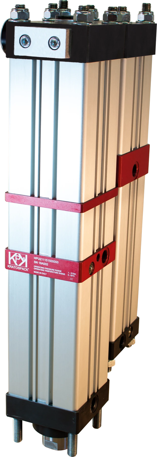
HPU - HPX
Pneumatic cylinder and hydraulic multiplier mounted in parallel

HRU - HRX
Pneumatic cylinder and hydraulic multiplier mounted in parallel
Variants

V - End-of-stroke valve
On the Pneumatic-Hydraulic Power Units – H Series KRATOSPACK, with the exception of HRU-HRX Series, a stroke-limiting valve can be fitted. By turning a thumbwheel located on the outside of the unit, the user can limit the operating stroke of the output rod.
The valve regulates the amount of oil inside the tank, adjusting the rod stroke with extreme precision.
The user can therefore fine-tune the working stroke according to the characteristics of the workpiece. The standard adjustment range of the limiting valve is 0–15 mm.
The BONESI PNEUMATIK technical and sales team is available to assess each customer’s specific requirements.
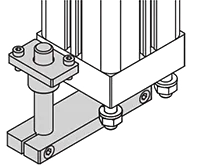
A – Anti-rotation unit
The anti-rotation unit available for the Pneumatic-Hydraulic Power Units – H Series KRATOSPACK prevents the rod from rotating during the approach and operating strokes.
This mechanical component is recommended when the accessory mounted on the rod needs to maintain the same orientation during operating cycles.
E | L | C | F - Load cell unit
A load cell is an essential component when feedback is required on the operating cycle set on the power unit.
By combining the load cell with a process controller, the user can set the operating curve on the control device according to the specifications of the workpiece. At the end of the cycle, the device will indicate whether the set parameters have been met (compliant part) or which parameters have exceeded the tolerance limit (non-compliant part).
Different load cells and control devices are available to meet customer requirements. As standard, when paired with the load cell, the unit is supplied with an anti-rotation device.
The BONESI PNEUMATIK technical and sales team is available to assess each customer’s specific requirements.

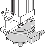
C | M | R - Spigots and Mounting Hubs
Accessories can be fitted to the Pneumatic-Hydraulic Power Units – H Series KRATOSPACK either using the metric threaded hole on the rod or via accessories that are suitably sized for the unit.
The standard accessories available from BONESI PNEUMATIK are:
- Male shank
- Shank and die-holder hub
- Radial die holder
The BONESI PNEUMATIK technical and sales team is available to assess each customer’s specific requirements.

F - Front-mounting flange
As standard, the Pneumatic-Hydraulic Power Units – H Series KRATOSPACK are supplied with front-protruding tie rods, allowing the unit to be secured directly to the customer’s structure.
Alternatively, the unit can be equipped with a front interface flange.
The BONESI PNEUMATIK technical and sales team is available to assess each customer’s specific requirements.
Applications
Thanks to their unique design features, the H Series – KRATOSPACK power units are particularly well-suited to industrial automation for a broad range of tasks, including clamping, riveting, bending, marking, pressing, shearing, punching, deep drawing, re-forming, assembling, crimping, edging, clinching …
One of the key features that sets the Series H – KRATOSPACK power units apart is that there are no restrictions on their mounting position.
RIVETTING AND CLINCHING
PUNCHING AND MARKING
SHEARING AND PERFORATING
DEEP DRAWING, BENDING AND PRESSING
Main phases of operation
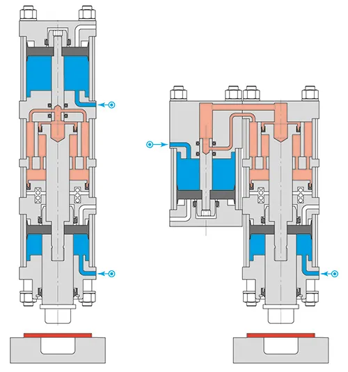
1 - Downtime
During downtime, the unit’s rod is held in position by the pneumatic action in the approach and working chambers.
At this stage, the workpiece is placed beneath the unit in the work area.
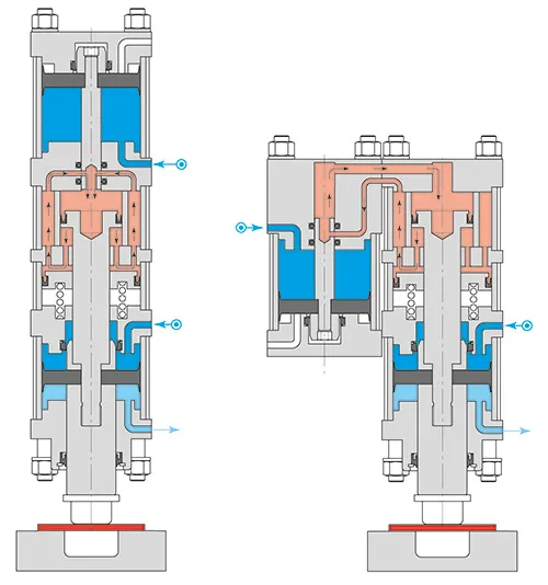
2 – Rapid approach phase
During the rapid approach phase, the rod comes into contact with the workpiece by means of the pneumatic feed system. The oil inside the unit freely circulates (at low pressure). Generally, at this stage, the workpiece does not undergo any permanent deformation.
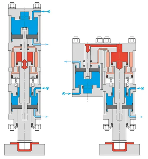
3 - Uptime
During the work phase, the force is amplified by engaging the amplifier stem and subsequently sealing the high-pressure oil chamber. The oil can no longer flow freely, transferring all the force directly to the workpiece. In this phase, the workpiece is subject to permanent deformation.
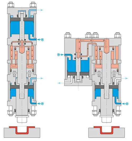
4 – Rapid return phase
Once the operation is complete, the rapid return phase dissipates the force exerted and activates the valves that return the rod to its initial position. The final stages of the return stroke involve the operation of the pneumatic decelerator.
At this stage, the workpiece can be handled to complete the work cycle.
Download the information material
Download our catalogues and brochures to find all the information you need – technical details, design stages and bespoke solutions tailored to your needs. Choose the topic of interest and browse all the latest news at your leisure, wherever you are.
Sei interessato ai nostri prodotti?
Compila il form e verrai ricontattato dal nostro servizio clienti in grado di ascoltare la tua richiesta e fornirti la risposta adeguata.